Difference between revisions of "Hardware:RF"
| (18 intermediate revisions by 3 users not shown) | |||
| Line 1: | Line 1: | ||
'''RF Coil''' | '''RF Coil''' | ||
---- | ---- | ||
| − | [[File:rfcoil.jpg| | + | [[File:rfcoil.jpg|400px|thumb|right|RF coil in copper shielded box]] |
| − | The RF coil for this system is used for transmitting the excitation pulse to get the magnetization precessing and to detect the MRI signal thru the Faraday detection principle. The coil is part of a resonant circuit that is tuned to the Larmor frequency of the B0 magnet. The coil is a solenoid which the NMR tubes fit into snuggly; it is contained in a plastic case which is wrapped in copper foil to shield against external RF noise sources. | + | The RF coil for this system is used for transmitting the excitation pulse to get the magnetization precessing and to detect the MRI signal thru the Faraday detection principle. The coil is part of a resonant circuit that is tuned to the Larmor frequency of the B0 magnet. The coil is a solenoid which the NMR tubes fit into snuggly; it is contained in a plastic case which is wrapped in copper foil to shield against external RF noise sources. The length of the solenoid is a tradeoff between B1 homogeneity (longer is better) and the size of the imaging volume. If the solenoid is too long, signal from water outside the imaging volume that lies in the nonlinear region of the gradient coil field profile will warp into the image and cause artifacts. |
| + | |||
| + | [[File:IMG_7652.JPG|400px|thumb|right|Close-up of RF coil showing approx. size: ~7 turns of wire, 14mm dia. along X, 11mm length along Y direction. Teflon tubing is used around the wire to set the spacing between turns.]] | ||
---- | ---- | ||
'''TR Switch''' | '''TR Switch''' | ||
---- | ---- | ||
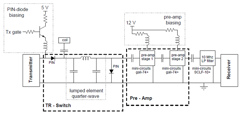
| − | The RF coil is used for 2 things: transmitting the RF pulse and receiving the MRI signal. This means that it should sometimes be connected to the transmit amplifier and sometimes be connected to the receive amplifier. This TR switch uses pin diodes and a lumped quarterwave line to effectively switch the coil connection between the two amplifiers. | + | The RF coil is used for 2 things: transmitting the RF pulse and receiving the MRI signal. This means that it should sometimes be connected to the transmit amplifier and sometimes be connected to the receive amplifier. This TR switch uses pin diodes and a lumped quarterwave line to effectively switch the coil connection between the two amplifiers, as shown in [https://tabletop.martinos.org/images/1/1b/Picture1.png this schematic diagram]. |
| + | |||
---- | ---- | ||
'''Receive amplifier''' | '''Receive amplifier''' | ||
---- | ---- | ||
| − | The NMR signal from the coil is very small, so a a pre-amplifier with a low noise figure is needed as the receive amplifier. A 2 stage amplifier was designed using [http://www.minicircuits.com/pdfs/GALI-74+.pdf Gali-74+ Monolithic Amplifier] from Minicircuits. The TR switch and pre-amplifier circuit were combined in a single PCB. | + | The NMR signal from the coil is very small, so a a pre-amplifier with a low noise figure is needed as the receive amplifier. A 2 stage amplifier was designed using [http://www.minicircuits.com/pdfs/GALI-74+.pdf Gali-74+ Monolithic Amplifier] from Minicircuits. The TR switch and pre-amplifier circuit were combined in a single PCB. [https://tabletop.martinos.org/images/4/48/TR_switch_and_preamp.zip Click here] to download the Eagle board files for the TR Switch PCB. |
| + | |||
| + | ---- | ||
| + | '''Power amplifier''' | ||
| + | ---- | ||
| + | The RF pulse created by the Medusa console is amplified by a 1,2W broadband RF power amplifier (MiniCircuits ZHL-3A). Because we had some trouble with the carrier frequency coming through the transmit side even when the pulse was "off" at the console, we found we needed to gate the power to the ZHL-3A using the gating pulse from the console so that the ZHL-3A only receives power during the RF pulse. This also prevents the ZHL-3A from dissipating heat between RF pulses. | ||
| + | |||
| + | As an alternative RFPA, we have also had success with the MHW592 Motorola RFPA. We prepared an in-house PCB daughter board to house the MWH592 module. The board can be downloaded [http://rflab.martinos.org/index.php?title=Low-cost_1_Watt_RF_power_amplifier_(in_progress) at this link]. The MHW592 is an obsolete component but is still available from vendors on eBay, etc. This RFPA provides faster power-on times for unblanking using our simple unblanking method of cutting power to the RFPA module with a TIP32 transistor. | ||
Latest revision as of 12:53, 19 May 2022
RF Coil

The RF coil for this system is used for transmitting the excitation pulse to get the magnetization precessing and to detect the MRI signal thru the Faraday detection principle. The coil is part of a resonant circuit that is tuned to the Larmor frequency of the B0 magnet. The coil is a solenoid which the NMR tubes fit into snuggly; it is contained in a plastic case which is wrapped in copper foil to shield against external RF noise sources. The length of the solenoid is a tradeoff between B1 homogeneity (longer is better) and the size of the imaging volume. If the solenoid is too long, signal from water outside the imaging volume that lies in the nonlinear region of the gradient coil field profile will warp into the image and cause artifacts.

TR Switch
The RF coil is used for 2 things: transmitting the RF pulse and receiving the MRI signal. This means that it should sometimes be connected to the transmit amplifier and sometimes be connected to the receive amplifier. This TR switch uses pin diodes and a lumped quarterwave line to effectively switch the coil connection between the two amplifiers, as shown in this schematic diagram.
Receive amplifier
The NMR signal from the coil is very small, so a a pre-amplifier with a low noise figure is needed as the receive amplifier. A 2 stage amplifier was designed using Gali-74+ Monolithic Amplifier from Minicircuits. The TR switch and pre-amplifier circuit were combined in a single PCB. Click here to download the Eagle board files for the TR Switch PCB.
Power amplifier
The RF pulse created by the Medusa console is amplified by a 1,2W broadband RF power amplifier (MiniCircuits ZHL-3A). Because we had some trouble with the carrier frequency coming through the transmit side even when the pulse was "off" at the console, we found we needed to gate the power to the ZHL-3A using the gating pulse from the console so that the ZHL-3A only receives power during the RF pulse. This also prevents the ZHL-3A from dissipating heat between RF pulses.
As an alternative RFPA, we have also had success with the MHW592 Motorola RFPA. We prepared an in-house PCB daughter board to house the MWH592 module. The board can be downloaded at this link. The MHW592 is an obsolete component but is still available from vendors on eBay, etc. This RFPA provides faster power-on times for unblanking using our simple unblanking method of cutting power to the RFPA module with a TIP32 transistor.