Difference between revisions of "Hardware:Gradient coil"
| Line 1: | Line 1: | ||
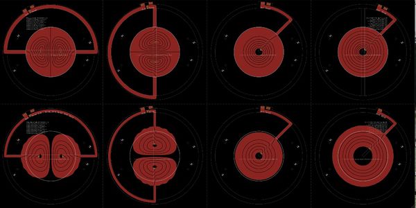
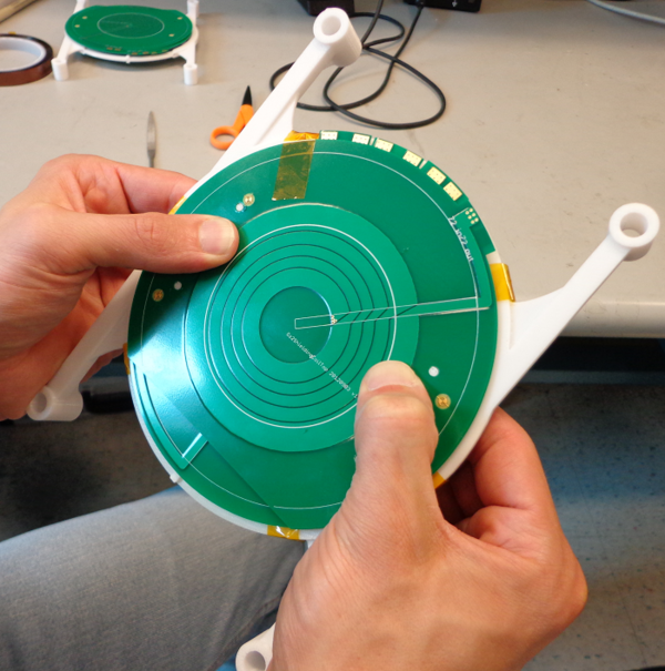
The gradient coils generate the linear gradient fields that are used for imaging. They produce a magnetic field in the z direction which changes linearly with position with a slope of14G/cm when driven with 1 amp of current. With 2 A, the slope is 28G/cm so we refer to the sensitivity of the gradients as 14G/(cm A). The gradient coils for this system are contained on a printed circuit board that is inserted into the magnet bore leaving a space just over 1cm for the sample and RF detector/exciter coil. | The gradient coils generate the linear gradient fields that are used for imaging. They produce a magnetic field in the z direction which changes linearly with position with a slope of14G/cm when driven with 1 amp of current. With 2 A, the slope is 28G/cm so we refer to the sensitivity of the gradients as 14G/(cm A). The gradient coils for this system are contained on a printed circuit board that is inserted into the magnet bore leaving a space just over 1cm for the sample and RF detector/exciter coil. | ||
The gradient coil isocurrent contours were calculated by Maxim Zaitsev and Feng Jia of Univ. Freiburg. The contours were converted to circuitboard traces by Cris LaPierre at MGH. The gradients are implemented as a shielded planar coils, so an inner set of primary coils spaced by about 1cm and the shield coils placed at the magnet poles. | The gradient coil isocurrent contours were calculated by Maxim Zaitsev and Feng Jia of Univ. Freiburg. The contours were converted to circuitboard traces by Cris LaPierre at MGH. The gradients are implemented as a shielded planar coils, so an inner set of primary coils spaced by about 1cm and the shield coils placed at the magnet poles. | ||
| + | The inductance of the final x, y, z and z^2 coils are: XX, YY, ZZ, Z2 | ||
[[File:Gradient_boards_smaller_jpg.jpg|600px|thumb|right|]] | [[File:Gradient_boards_smaller_jpg.jpg|600px|thumb|right|]] | ||
[[File:gradientcoil.png|600px|thumb|right|]] | [[File:gradientcoil.png|600px|thumb|right|]] | ||
Revision as of 14:49, 22 August 2013
The gradient coils generate the linear gradient fields that are used for imaging. They produce a magnetic field in the z direction which changes linearly with position with a slope of14G/cm when driven with 1 amp of current. With 2 A, the slope is 28G/cm so we refer to the sensitivity of the gradients as 14G/(cm A). The gradient coils for this system are contained on a printed circuit board that is inserted into the magnet bore leaving a space just over 1cm for the sample and RF detector/exciter coil. The gradient coil isocurrent contours were calculated by Maxim Zaitsev and Feng Jia of Univ. Freiburg. The contours were converted to circuitboard traces by Cris LaPierre at MGH. The gradients are implemented as a shielded planar coils, so an inner set of primary coils spaced by about 1cm and the shield coils placed at the magnet poles. The inductance of the final x, y, z and z^2 coils are: XX, YY, ZZ, Z2

