Difference between revisions of "Hardware:Magnet"
| (38 intermediate revisions by the same user not shown) | |||
| Line 1: | Line 1: | ||
| − | |||
== First Generation Magnet (CAS) == | == First Generation Magnet (CAS) == | ||
| Line 7: | Line 6: | ||
| − | [[File:magnet_figure_jpg.jpg|400px|thumb| | + | [[File:magnet_figure_jpg.jpg|400px|thumb|left|]] |
[[File:CAS_magnet.jpg|400px|thumb|right|]] | [[File:CAS_magnet.jpg|400px|thumb|right|]] | ||
| − | [[File:magnet_with_rf_coil_jpg.jpg|400px|thumb|right|First generation magnet | + | <br> |
| + | |||
| + | |||
| + | [[File:magnet_with_rf_coil_jpg.jpg|400px|thumb|right|First generation magnet with gradient coil and RF in place within the shielded box. B0 field strength is 0.19 Tesla.]] | ||
| + | |||
| + | |||
| + | |||
| + | <br> | ||
| + | <br> | ||
| + | <br> | ||
| + | |||
| + | |||
| + | |||
| + | |||
| + | |||
| + | |||
| + | |||
| + | |||
| + | |||
| + | |||
| + | |||
| + | |||
| + | |||
| + | |||
| + | |||
| + | |||
| + | |||
| + | |||
| + | |||
| + | |||
| + | |||
| + | |||
| + | |||
| + | |||
| + | |||
| + | |||
| + | |||
| + | |||
| + | |||
| + | |||
| + | |||
| + | |||
| + | |||
| + | |||
| Line 18: | Line 60: | ||
== Second Generation Magnet (MGH) == | == Second Generation Magnet (MGH) == | ||
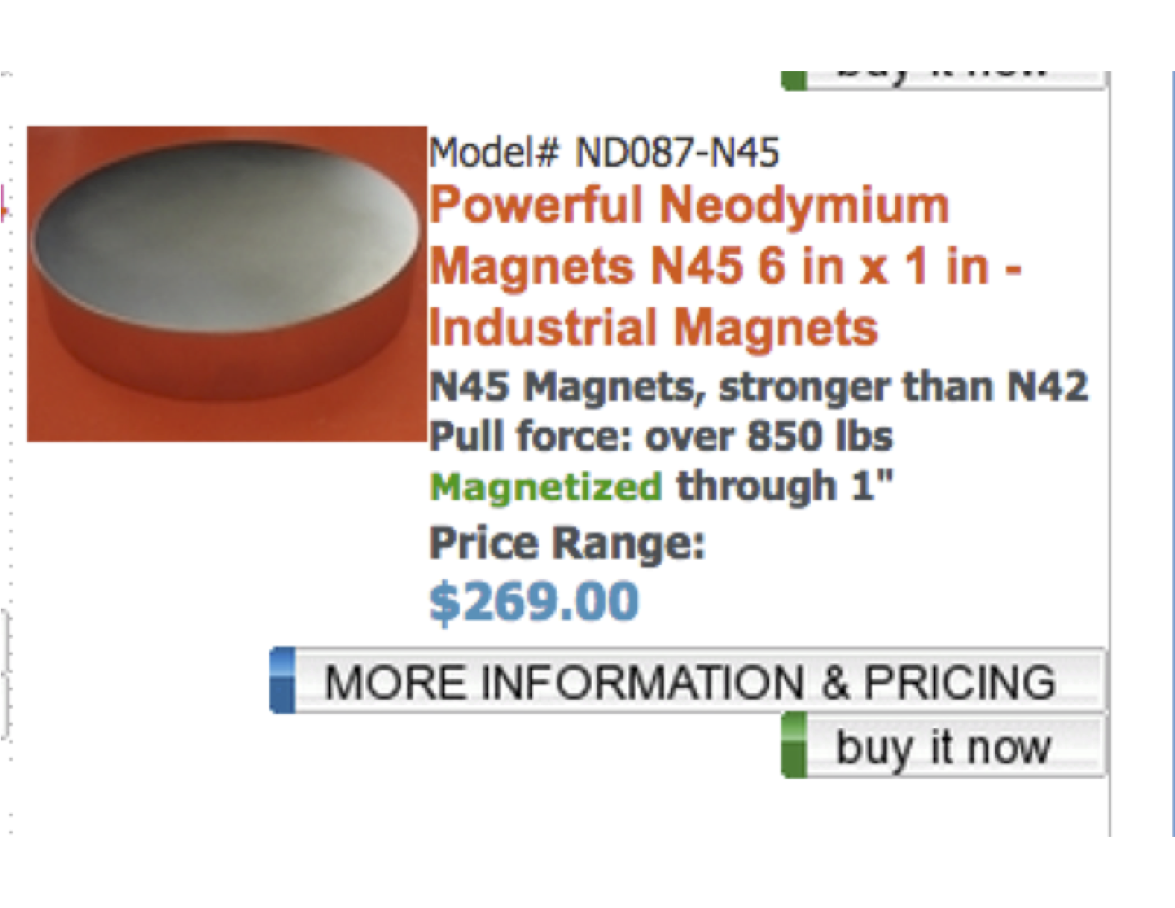
| − | A second generation magnet with 0.4T field strength was built at MGH in late 2014. The magnet uses a pair of 6" diameter, 1" thick discs of N45M ordered from [http://www.magnet4less.com/ Applied Magnets]. To see the specific magnetic pucks used [https://tabletop.martinos.org/ | + | A second generation magnet with 0.4T field strength was built at MGH in late 2014. It is modeled after the CAS magnet design. The 2nd-gen. magnet uses a pair of 6" diameter, 1" thick discs of N45M ordered from [http://www.magnet4less.com/ Applied Magnets]. To see the specific stock magnetic pucks used, [https://tabletop.martinos.org/images/2/2b/6inch_puck_magnet.png click here]. COMSOL simulations were used to optimize the pole piece and yoke dimensions for a combination of maximum field strength and homogeneity. |
| + | |||
| + | |||
| + | The yoke and pole pieces are machined from AISI 1018 steel. The preferred material would have been low carbon AISI 1008 steel but this grade of steel was not readily available in the needed stock sizes. Aluminum rings are used to center the pole piece on each magnetic puck. | ||
| + | |||
| + | '''''Extreme care must be taken''''' when attaching the magnetic pucks to the yokes or attaching the pole pieces to the magnetic pucks. Care must also be taken in bringing the two halves of the assembly together. The forces between these pieces are very strong at close distances and can cause serious injury. In our magnet, although the two pucks are attracted to one another, they are attracted much more strongly to the yoke. Epoxy and the aluminum guide rings ensure that the pucks do not move after final assembly. | ||
| + | |||
| + | |||
| + | [https://tabletop.martinos.org/images/3/36/Tabletop_Magnet_Simulation_V2.mph.zip Click here] to download COMSOL simulations of the magnetic field generated by this design. | ||
| + | |||
| + | |||
| + | [https://tabletop.martinos.org/index.php/File:PDF_magnet_drawings.zip Click here] to download CAD drawings in PDF form. | ||
| + | |||
| + | |||
| + | [https://tabletop.martinos.org/index.php/File:Inventor_CAD_drawings_magnet.zip Click here] to download CAD drawings in Autodesk Inventor format. | ||
| + | |||
| + | |||
| + | [[File:Optimized tabletop crosssection view.png|400px|thumb|left|Magnet cross section dimensions. Depth is 6.25".]] | ||
| + | |||
| + | |||
| + | [[File:Secon_generation_magnet_photo_MGH.JPG|400px|thumb|right|Second generation magnet shown with gradient and RF coil installed. B0 field strength is 0.4 Tesla.]] | ||
| + | |||
| + | |||
| + | |||
| + | |||
| − | + | <br> | |
| + | <br> | ||
| + | <br> | ||
| + | <br> | ||
| + | <br> | ||
| − | + | == Magnet building tutorial == | |
| − | [ | + | [http://tabletop.martinos.org/files/maker_B0_educational_stockmann_ismrm_2018_V5_FINAL.pptx Click here] to download slides from the "Maker: B0" magnet-building tutorial from ISMRM 2018. This tutorial shows you all the steps for safely building the Second Generation Magnet described above. |
Latest revision as of 12:30, 5 May 2020
First Generation Magnet (CAS)
The B0 field is created by a small 0.19T permanent magnet weighing about 13kg. The two N45M (NdFeB) rare-earth magnet disks are 15cm in diameter and held 4cm apart with an iron yoke, which also provides a flux-return path for the magnetic field, containing the field to the gap between the pole pieces (and inside the iron). The magnet was designed and constructed by the group of Prof. Yang Wenhui of the Institute of Electrical Engineering of the Chinese Academy of Sciences in Beijing. Design and construction was supervised by Wang Zheng. The CAS group also shimmed the magnet to ~50ppm homogeneity over 1cm DSV. The right photo shows the magnet in the shielded box with the RF coil and 1cm dia. sample tube in place.


Second Generation Magnet (MGH)
A second generation magnet with 0.4T field strength was built at MGH in late 2014. It is modeled after the CAS magnet design. The 2nd-gen. magnet uses a pair of 6" diameter, 1" thick discs of N45M ordered from Applied Magnets. To see the specific stock magnetic pucks used, click here. COMSOL simulations were used to optimize the pole piece and yoke dimensions for a combination of maximum field strength and homogeneity.
The yoke and pole pieces are machined from AISI 1018 steel. The preferred material would have been low carbon AISI 1008 steel but this grade of steel was not readily available in the needed stock sizes. Aluminum rings are used to center the pole piece on each magnetic puck.
Extreme care must be taken when attaching the magnetic pucks to the yokes or attaching the pole pieces to the magnetic pucks. Care must also be taken in bringing the two halves of the assembly together. The forces between these pieces are very strong at close distances and can cause serious injury. In our magnet, although the two pucks are attracted to one another, they are attracted much more strongly to the yoke. Epoxy and the aluminum guide rings ensure that the pucks do not move after final assembly.
Click here to download COMSOL simulations of the magnetic field generated by this design.
Click here to download CAD drawings in PDF form.
Click here to download CAD drawings in Autodesk Inventor format.


Magnet building tutorial
Click here to download slides from the "Maker: B0" magnet-building tutorial from ISMRM 2018. This tutorial shows you all the steps for safely building the Second Generation Magnet described above.