Difference between revisions of "Hardware:Lab"
Jump to navigation
Jump to search
| Line 1: | Line 1: | ||
[[File:FID_GUI_screenshot.jpg|400px|thumb|right|figure 1. so and so]] | [[File:FID_GUI_screenshot.jpg|400px|thumb|right|figure 1. so and so]] | ||
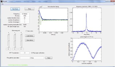
| + | To the right is a screen shot of the "FID GUI" which allows the digitized FID to be displaced as well as the spectrum of that FID. It also has a shimming tool to adjust the shim offset currents to try to improve the spectral linewidth. There is also a flip angle calibrator which steps thru RF pulse amplitudes from 0 to full power and plots the signal amplitude as a function of power. | ||
Revision as of 15:01, 22 August 2013
To the right is a screen shot of the "FID GUI" which allows the digitized FID to be displaced as well as the spectrum of that FID. It also has a shimming tool to adjust the shim offset currents to try to improve the spectral linewidth. There is also a flip angle calibrator which steps thru RF pulse amplitudes from 0 to full power and plots the signal amplitude as a function of power.
