Difference between revisions of "Hardware:GPA"
m |
|||
| Line 2: | Line 2: | ||
---- | ---- | ||
[[File:GPASchematic.jpg|600px|thumb|right|figure 1. so and so]] | [[File:GPASchematic.jpg|600px|thumb|right|figure 1. so and so]] | ||
| − | The gradient amplifier is used to supply the current to the gradient coils. Since it's the fields we care about, and the fields are proportional to current, this amplifier can be viewed as a voltage to current transducer; it takes a voltage waveform from the console and creates a current proportional to that voltage in the gradient coil. It is similar to a common audio power amplifier except that it must also be able to output DC currents. It uses two [http://www.ti.com/lit/ds/symlink/opa549.pdf OPA 549] power op-amps in a bridged configuration. A current | + | The gradient amplifier is used to supply the current to the gradient coils. Since it's the fields we care about, and the fields are proportional to current, this amplifier can be viewed as a voltage to current transducer; it takes a voltage waveform from the console and creates a current proportional to that voltage in the gradient coil. It is similar to a common audio power amplifier except that it must also be able to output DC currents. It uses two [http://www.ti.com/lit/ds/symlink/opa549.pdf OPA 549] power op-amps in a bridged configuration. A current sensor compares the output current to the input voltage to ensure that the current itself is proportional to the desired signal. The current sensor consists of an [http://www.ti.com/lit/ds/symlink/ina105.pdf INA105] differential amplifier that measures the voltage across a small (0.1 ohm) resistor in series with the output. |
The figure to the right shows [https://gate.nmr.mgh.harvard.edu/wiki/Tabletop_MRI/images/3/32/MIT-GPA-v4.sch.pdf schematic for the GPA boards] generated in Eagle (version 6). Note that a separate A/D converter was used in the initial realization of the boards (DAC on the GPAs was not populated). | The figure to the right shows [https://gate.nmr.mgh.harvard.edu/wiki/Tabletop_MRI/images/3/32/MIT-GPA-v4.sch.pdf schematic for the GPA boards] generated in Eagle (version 6). Note that a separate A/D converter was used in the initial realization of the boards (DAC on the GPAs was not populated). | ||
Revision as of 18:50, 26 August 2013
Gradient Power Amplifier
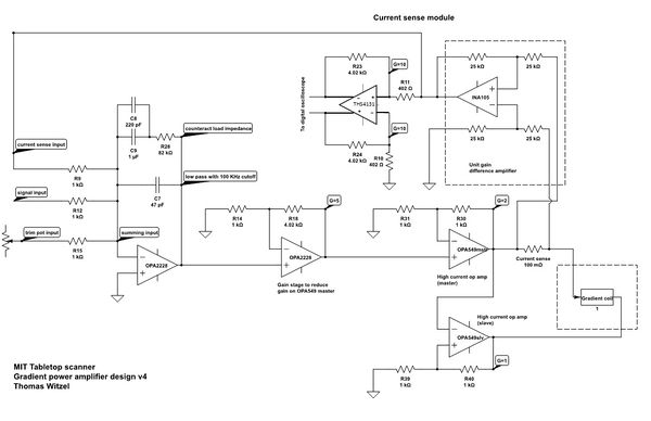
The gradient amplifier is used to supply the current to the gradient coils. Since it's the fields we care about, and the fields are proportional to current, this amplifier can be viewed as a voltage to current transducer; it takes a voltage waveform from the console and creates a current proportional to that voltage in the gradient coil. It is similar to a common audio power amplifier except that it must also be able to output DC currents. It uses two OPA 549 power op-amps in a bridged configuration. A current sensor compares the output current to the input voltage to ensure that the current itself is proportional to the desired signal. The current sensor consists of an INA105 differential amplifier that measures the voltage across a small (0.1 ohm) resistor in series with the output.
The figure to the right shows schematic for the GPA boards generated in Eagle (version 6). Note that a separate A/D converter was used in the initial realization of the boards (DAC on the GPAs was not populated).
Click here to download Eagle version 6 board (.brd) and schematic (.sch) files for the V3 GPA board (does not include on-board DAC).


