Difference between revisions of "Hardware:GPA"
| (39 intermediate revisions by 2 users not shown) | |||
| Line 2: | Line 2: | ||
---- | ---- | ||
| − | The gradient amplifier is used to supply the current to the gradient coils. Since it's the fields we care about, and the fields are proportional to current, this amplifier can be viewed as a voltage to current transducer; it takes a voltage waveform from the console and creates a current proportional to that voltage in the gradient coil. It is similar to a common audio power amplifier except that it must also be able to output DC currents. It uses two [http://www.ti.com/lit/ds/symlink/opa549.pdf OPA 549] power op-amps in a bridged configuration. A current sensor compares the output current to the input voltage to ensure that the current itself is proportional to the desired signal. | + | The gradient amplifier is used to supply the current to the gradient coils. Since it's the fields we care about, and the fields are proportional to current, this amplifier can be viewed as a voltage to current transducer; it takes a voltage waveform from the console and creates a current proportional to that voltage in the gradient coil. It is similar to a common audio power amplifier except that it must also be able to output DC currents. It uses two [http://www.ti.com/lit/ds/symlink/opa549.pdf OPA 549] power op-amps in a bridged configuration. A current sensor compares the output current to the input voltage to ensure that the current itself is proportional to the desired signal. The OPA549s can provide up to 8 amps of current, but in practice the current is limited by the duty cycle of the gradient waveform in the pulse sequence and the size of the heat sink used on the boards. |
| − | Two versions of the board have been used with the tabletop scanner. [[Hardware:GPA#Version 1 of the GPA board|Version 1]] | + | Two versions of the board have been used with the tabletop scanner. [[Hardware:GPA#Version 1 of the GPA board|Version 1]] uses separate digital-to-analog converter (DAC) boards and provides one output channel per GPA board. [[Hardware:GPA#Version 2 of the GPA board|Version 2]] simplified the wiring and reduced costs by placing three channels with integrated DAC stages onto a single PCB. Version 2 is plug-and-play compatible with the MEDUSA console digital gradient waveform output lines (RJ45 connector). |
| Line 12: | Line 12: | ||
== Version 1 of the GPA board == | == Version 1 of the GPA board == | ||
| + | A summing point op amp is used to compare the current sense resistor voltage to the input signal in order to adjust the output stage as needed. The current sensor consists of an [http://www.ti.com/lit/ds/symlink/ina105.pdf INA105] differential amplifier that measures the voltage across a small (0.1 ohm) resistor in series with the output. A differential amplifier on the INA105 output provides a differential signal that can be scoped to monitor the current sense resistor voltage. | ||
| + | [[File:updated_gpa_schematic_corrected_july_2020.png|300px|thumb|right|Version 1 Gradient Power Amplifier circuit providing a single channel of output current]] | ||
| + | |||
[https://tabletop.martinos.org/images/3/32/MIT-GPA-v4.sch.pdf Click here] to view the schematic for the GPA boards generated in Eagle (version 6). Note that a separate A/D converter was used in the initial realization of the boards (DAC on the GPAs was not populated). | [https://tabletop.martinos.org/images/3/32/MIT-GPA-v4.sch.pdf Click here] to view the schematic for the GPA boards generated in Eagle (version 6). Note that a separate A/D converter was used in the initial realization of the boards (DAC on the GPAs was not populated). | ||
| Line 18: | Line 21: | ||
[https://tabletop.martinos.org/images/b/b9/MIT-GPA-v3-fixed.zip Click here] to download Eagle version 6 board (.brd) and schematic (.sch) files for the V3 GPA board (does not include on-board DAC). | [https://tabletop.martinos.org/images/b/b9/MIT-GPA-v3-fixed.zip Click here] to download Eagle version 6 board (.brd) and schematic (.sch) files for the V3 GPA board (does not include on-board DAC). | ||
| − | + | ||
| + | |||
| + | |||
| + | |||
| + | |||
| + | |||
| Line 29: | Line 37: | ||
<!--[[File:Front panel photo.JPG|600px|thumb|left|Aluminum front panels were made using a water-jet cutter. [http://www.mouser.com/ProductDetail/Bud-Industries/NHC-14157/?qs=W%252bB5Pl59bv4hUDQy1Kr8cw== Hammond NHC-14157 enclosures] were used to house the GPAs and DACs. ]]--> | <!--[[File:Front panel photo.JPG|600px|thumb|left|Aluminum front panels were made using a water-jet cutter. [http://www.mouser.com/ProductDetail/Bud-Industries/NHC-14157/?qs=W%252bB5Pl59bv4hUDQy1Kr8cw== Hammond NHC-14157 enclosures] were used to house the GPAs and DACs. ]]--> | ||
| + | |||
| + | == Version 2 of the GPA board == | ||
| + | |||
| + | |||
| + | Version 2 of the board differs from Version 1 in the following ways: | ||
| + | <ol> | ||
| + | #) slightly simplified analog stage | ||
| + | #) on-board DACs | ||
| + | #) integration of three channels onto a single PCB. | ||
| + | </ol> | ||
| + | The analog stage still uses two OPA549 power op amps in a push-pull configuration. But instead of a summing point op amp (as in V1), two feedback loops are used across the current sense resistor. The circuit is designed to run on a 14V-to-24V supply rail, with higher rail voltages providing faster gradient slew rates for a given load inductance. The circuit specifications and performance are described in more detail in an ISMRM abstract: [http://cds.ismrm.org/protected/16MPresentations/abstracts/1157.html Arango et al., ISMRM 2016, p. 1157]. [https://tabletop.martinos.org/images/6/62/Arango_1157_8ch_shim_board_FINAL.pptx Click here] to download slides from the ISMRM talk. The circuit was originally designed for use as an 8ch open-source, low-cost current driver for multi-coil shimming and other applications. [https://rflab.martinos.org/index.php/Current_driver:Current_driver Click here] for information about the 8ch board, including software for simulating the open loop transfer function and step response of the circuit into a specified load (useful for choosing the load impedance compensation circuit values). | ||
| + | |||
| + | |||
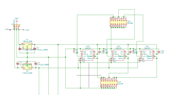
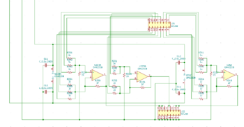
| + | [[File:V2 gpa single channel schematic.png|500px|thumb|left|Analog stage schematic for GPA Version 2. Stability is ensured by compensating the gradient coil load inductance using a lead compensator in the feedback loops. To compensate different loads, only two capacitors need to be changed as indicated in the yellow box. Circuit was designed and laid out by Jacob White and Nicolas Arango at MIT.]] | ||
| + | |||
| + | |||
| + | |||
| + | [[https://tabletop.martinos.org/images/8/86/GPA_3ch_tabletop_shimboard_RevB_V8_2.zip Click here]] to download Eagle version 6 board (.brd) and schematic (.sch) files for the GPA board with on-board DACs (Rev B). GERBER files for board production are also included. | ||
| + | |||
| + | |||
| + | |||
| + | |||
| + | |||
| + | |||
| + | |||
| + | |||
| Line 35: | Line 69: | ||
| − | |||
| − | Version 2 | + | <gallery caption="3ch GPA board and enclosure" widths="350px" heights="250px" perrow="2"> |
| + | image:Version 2 GPA photo.JPG|GPA board with 3 parallel analog stages each connected to a DAC. RJ45 connectors accept [[https://tabletop.martinos.org/index.php/Hardware:Console MEDUSA console]] digital SPI outputs for the X, Y, and Z gradient axes. | ||
| + | image:Version 2 GPA enclosure.JPG|The 3ch GPA board installed in enclosure. Powered by a 24V, 25A switching supply along with a small -15V supply for the digital stage ICs. (Heat sinks and fan are not yet installed in this photo). | ||
| + | </gallery> | ||
| + | ''Known bugs in Rev B'': (1.) The LT1920 current sense buffer op amp is not working and requires debugging. The positive rail of the op amp was mistakenly connected to the +24V rail instead of the regulated +12V rail. We recommend using the board without the LT1920 for the time being until a bug fix is posted. (2.) The stencil for the Avago HCPL-0738 optical isolator showing the location of Pin 1 is incorrect. The stencil does not correspond to a possible location where Pin 1 can be located. Instead, the stencil should be lined up with Pin 4 on the IC. | ||
== Gradient Filter == | == Gradient Filter == | ||
| Line 59: | Line 96: | ||
[[File:gradient_filter_photo.png|400px|thumb|none|Sample of populated filter board (v1)]] | [[File:gradient_filter_photo.png|400px|thumb|none|Sample of populated filter board (v1)]] | ||
| + | |||
| + | == 3ch GPA using 8ch Shim Board == | ||
| + | Using the existing Rev C shim amplifier board, this GPA gives 3 channels of 8+ Amps of current. Channels X and Z have a gain of 5.5 A/V, and channel Y has a gain of 3.75 A/V. The GPA is powered with two series 24V supplies. Three BNC connectors take voltage waveform inputs at audio frequencies output to three banana plug outputs. An ammeter tracks total current use for the board, with a typical quiescent current of 600 mA. There are current sense pins available per channel at 1 V/A. | ||
| + | [[File:3ch_gpa.jpg|300px|thumb|right|3ch gradient amplifier built from a modified 8ch shim amplifier board]] | ||
| + | |||
| + | <gallery widths="350px" heights="250px"> | ||
| + | image:3ch_inputs.jpg|3 BNC ports (X, Y, Z) take differential voltage waves and output 8+ Amps from 3 banana plug outputs | ||
| + | image:3ch_insides.jpg|The Rev C shim amplifier board is modified with a buffer on the input and output, along with ganging channels together to raise current limits (3 channels for X, Z; 2 for Y) | ||
| + | </gallery> | ||
| + | |||
| + | To use the Rev C shim amplifier board, the GPA groups channels together (3 for X, Z, 2 for Y) to raise current limits. The shim pcb is fitted with an additional buffer board that attaches on top of it. The buffer board buffers the inputs and current sense outputs to avoid grounding issues. The inputs and outputs to the buffer board are wires that are jumped onto the board. | ||
| + | |||
| + | <gallery widths="350px" heights="250px"> | ||
| + | image:3ch_buffer_placement.jpg|Buffer board placed on shim amplifier pcb | ||
| + | image:buffer_pcb.png|Buffer board pcb layout | ||
| + | image:buffer_schematic.png|Buffer board schematic, containing input and current sense output buffers | ||
| + | image:buffer_input_schematic.png|Input buffer, passing the input through a unity-gain buffer | ||
| + | image:buffer_current_sense.png|Current sense voltage adder and buffer, tracking the current sense resistor voltage drops to a gain of 1 V/A per channel (X, Y, Z) | ||
| + | </gallery> | ||
| + | |||
| + | The Rev C shim board requires a tuned compensation feedback loop to avoid signal ringing. This is dependent on the load -- for the Halbach scanner, a tabletop MR scanner with ~400 uH coil inductance and ~2 Ohm resistance, the feedback capacitors are currently 1470 pF. This requires switching out components to change. | ||
| + | |||
| + | [[Media:buffer_board.zip|Buffer board KiCAD files]] | ||
Latest revision as of 13:29, 29 September 2020
Gradient Power Amplifier
The gradient amplifier is used to supply the current to the gradient coils. Since it's the fields we care about, and the fields are proportional to current, this amplifier can be viewed as a voltage to current transducer; it takes a voltage waveform from the console and creates a current proportional to that voltage in the gradient coil. It is similar to a common audio power amplifier except that it must also be able to output DC currents. It uses two OPA 549 power op-amps in a bridged configuration. A current sensor compares the output current to the input voltage to ensure that the current itself is proportional to the desired signal. The OPA549s can provide up to 8 amps of current, but in practice the current is limited by the duty cycle of the gradient waveform in the pulse sequence and the size of the heat sink used on the boards.
Two versions of the board have been used with the tabletop scanner. Version 1 uses separate digital-to-analog converter (DAC) boards and provides one output channel per GPA board. Version 2 simplified the wiring and reduced costs by placing three channels with integrated DAC stages onto a single PCB. Version 2 is plug-and-play compatible with the MEDUSA console digital gradient waveform output lines (RJ45 connector).
Email jaystock@nmr.mgh.harvard.edu with any questions.
Version 1 of the GPA board
A summing point op amp is used to compare the current sense resistor voltage to the input signal in order to adjust the output stage as needed. The current sensor consists of an INA105 differential amplifier that measures the voltage across a small (0.1 ohm) resistor in series with the output. A differential amplifier on the INA105 output provides a differential signal that can be scoped to monitor the current sense resistor voltage.

Click here to view the schematic for the GPA boards generated in Eagle (version 6). Note that a separate A/D converter was used in the initial realization of the boards (DAC on the GPAs was not populated).
Click here to download Eagle version 6 board (.brd) and schematic (.sch) files for the V3 GPA board (does not include on-board DAC).
- Gradient Power Amplifier enclosure
GPA boards mounted in enclosure with power supplies, terminal blocks, and digital-to-analog converter boards. The boards were run on bipolar +15V and -15V rails provided by CUI switching supplies. On-board regulators provide +12V, -12V, and +5V for powering the small ICs. The +12V fan is powered by a small JST connector on the CUI supplies.
Aluminum front panels were made using a water-jet cutter. Hammond NHC-14157 enclosures were used to house the GPAs and DACs. Click here for DXF file for front panel cut-outs. Note that Version 2 of the GPA board requires a horizontal slot for the RJ45 connectors instead of the vertical slot used here.


Version 2 of the GPA board
Version 2 of the board differs from Version 1 in the following ways:
- ) slightly simplified analog stage
- ) on-board DACs
- ) integration of three channels onto a single PCB.
The analog stage still uses two OPA549 power op amps in a push-pull configuration. But instead of a summing point op amp (as in V1), two feedback loops are used across the current sense resistor. The circuit is designed to run on a 14V-to-24V supply rail, with higher rail voltages providing faster gradient slew rates for a given load inductance. The circuit specifications and performance are described in more detail in an ISMRM abstract: Arango et al., ISMRM 2016, p. 1157. Click here to download slides from the ISMRM talk. The circuit was originally designed for use as an 8ch open-source, low-cost current driver for multi-coil shimming and other applications. Click here for information about the 8ch board, including software for simulating the open loop transfer function and step response of the circuit into a specified load (useful for choosing the load impedance compensation circuit values).

[Click here] to download Eagle version 6 board (.brd) and schematic (.sch) files for the GPA board with on-board DACs (Rev B). GERBER files for board production are also included.
- 3ch GPA board and enclosure
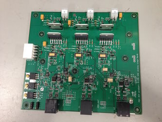
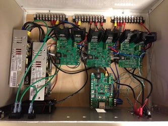
GPA board with 3 parallel analog stages each connected to a DAC. RJ45 connectors accept [MEDUSA console] digital SPI outputs for the X, Y, and Z gradient axes.
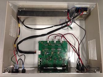
The 3ch GPA board installed in enclosure. Powered by a 24V, 25A switching supply along with a small -15V supply for the digital stage ICs. (Heat sinks and fan are not yet installed in this photo).


Known bugs in Rev B: (1.) The LT1920 current sense buffer op amp is not working and requires debugging. The positive rail of the op amp was mistakenly connected to the +24V rail instead of the regulated +12V rail. We recommend using the board without the LT1920 for the time being until a bug fix is posted. (2.) The stencil for the Avago HCPL-0738 optical isolator showing the location of Pin 1 is incorrect. The stencil does not correspond to a possible location where Pin 1 can be located. Instead, the stencil should be lined up with Pin 4 on the IC.
Gradient Filter
6th order butterworth low pass filters were added to the lines leading to the gradients.
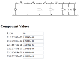
Filter design and component values for gradient filter. Note that R1 and R2 are not necessary in the final assembly.
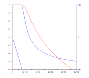
Simulated roll off performance of the filter as designed


The final version of these files can be downloaded as Eagle 5.11.0 and Gerber (for having the boards manufactured).
Note: Inductors were selected based on lead time and inductance and NOT on the package. Any inductor with similar inductance would work. The board was specifically designed for the following: 2.1 uH, 7.7 uH and 5.6 uH.
Note: All capacitor pads are for a 1206 package. There are four pads at each spot to allow for using multiple capacitors to obtain the specified value.

3ch GPA using 8ch Shim Board
Using the existing Rev C shim amplifier board, this GPA gives 3 channels of 8+ Amps of current. Channels X and Z have a gain of 5.5 A/V, and channel Y has a gain of 3.75 A/V. The GPA is powered with two series 24V supplies. Three BNC connectors take voltage waveform inputs at audio frequencies output to three banana plug outputs. An ammeter tracks total current use for the board, with a typical quiescent current of 600 mA. There are current sense pins available per channel at 1 V/A.

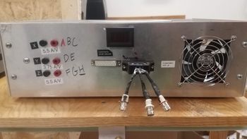
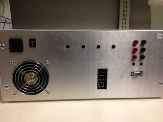
3 BNC ports (X, Y, Z) take differential voltage waves and output 8+ Amps from 3 banana plug outputs
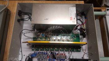
The Rev C shim amplifier board is modified with a buffer on the input and output, along with ganging channels together to raise current limits (3 channels for X, Z; 2 for Y)


To use the Rev C shim amplifier board, the GPA groups channels together (3 for X, Z, 2 for Y) to raise current limits. The shim pcb is fitted with an additional buffer board that attaches on top of it. The buffer board buffers the inputs and current sense outputs to avoid grounding issues. The inputs and outputs to the buffer board are wires that are jumped onto the board.
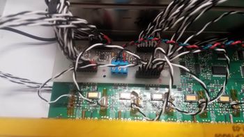
Buffer board placed on shim amplifier pcb
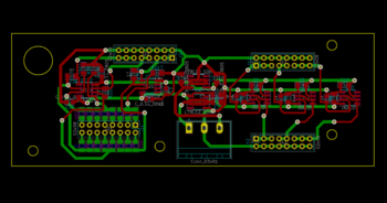
Buffer board pcb layout
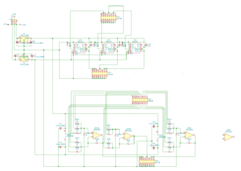
Buffer board schematic, containing input and current sense output buffers
Input buffer, passing the input through a unity-gain buffer
Current sense voltage adder and buffer, tracking the current sense resistor voltage drops to a gain of 1 V/A per channel (X, Y, Z)


The Rev C shim board requires a tuned compensation feedback loop to avoid signal ringing. This is dependent on the load -- for the Halbach scanner, a tabletop MR scanner with ~400 uH coil inductance and ~2 Ohm resistance, the feedback capacitors are currently 1470 pF. This requires switching out components to change.